آی پی امداد
abtahi

درخواست: فرستنده ها و گيرنده

2elyas

VIP+ افتخاری
کاربر
2012-01-30
401
1,549
باسلام خدمت استاد عزیزم آقای jfrrasمن یه میکرفن بیسیم با قدرت تقریبی 3 وات طراحی کردم و مونتاز کردم کیفیتش خوبه ولی تنها مشکلش اینه که روی دستگاه های نزدیک کنارش نویز میریزه.میخواستم ببینم راهی برای از بین بردن این نویز هست یا اینکه تمام فرستنده های با قدرت این مشکلو دارن؟فرکانس میکرفن من 235 مگا هرتزه.با تشکر
 

jfrras

مدير انجمن تخصصی الکترونیک
مدیر تالار
2007-04-13
3,117
74,139
48
ایران
باسلام خدمت استاد عزیزم آقای jfrrasمن یه میکرفن بیسیم با قدرت تقریبی 3 وات طراحی کردم و مونتاز کردم کیفیتش خوبه ولی تنها مشکلش اینه که روی دستگاه های نزدیک کنارش نویز میریزه.میخواستم ببینم راهی برای از بین بردن این نویز هست یا اینکه تمام فرستنده های با قدرت این مشکلو دارن؟فرکانس میکرفن من 235 مگا هرتزه.با تشکر

سلام
عکس نقشه و مونتاژ شده اش رو برام بفرست
یه نگاهی بکنم .تشکر
 

اقای مهندس

کاربران vip(افتخاری)
vip افتخاری
کاربر
2011-08-02
533
2,463
پاسخ : 10 وات و 50 وات فرستنده fm

دوست من چندتا مدار جالب تو آرشیو دارم در چند روز آینده یکی که ساده باشه تقدیم می کنم .یعنی زیاد مدارش شلوغ نباشه.
دوست خوبم چندروز الان باید گذشته باشها...
 

jfrras

مدير انجمن تخصصی الکترونیک
مدیر تالار
2007-04-13
3,117
74,139
48
ایران
سلام دوست من

ساده ترین واکی تاکی برای شما


توضیحات به زبان اصلی
A simple radio 27 MHz with an amplitude modulation.

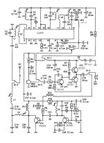
The radio station operates at a fixed frequency in the range of 27 MHz with amplitude modulation. Sure range between two such stations in the open area is about 1000 meters from the station is powered autonomous source voltage of 9 V (two galvanic battery of 4.5 V each). Schematic diagram of the radio station is shown in Fig.
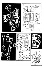
cf.jpgStructurally, the station consists of three main parts: the reception path, built on a chip TCA440, transmitting tract, performed by two-stage scheme of the transmitter, and a universal amplifier AF, who works at reception as UMZCH and transfer - as a modulation amplifier. Switching between "transmit-receive" made ​​the switch S 1. The switch does not lock in the free state (as in the diagram) is in the "reception".In receiving the signal from the antenna through the contacts of S 1.4 and the capacitor C1 is fed to the input circuit L 1 C 2 is tuned to the carrier frequency. Dedicated signal through the coil L 2, due to the input of the symmetrical inverter circuits A1 (pins 1 and 2).In the local oscillator circuit works circuit L 3 C 4, tuned to a frequency oscillator and a quartz resonator Q 1, the resonance frequency is equal to twice the LO frequency, or below this frequency. Intermediate frequency signal is allocated in the loop L 4 C 6 and the coil due to the L 5 through the coupling capacitor C7 to the input of IF amplifier chip. This scheme is not used piezoceramic filter, this leads to a decrease in selectivity for adjacent channel, but allows you to choose a non-standard values ​​of the intermediate frequency in the range 300 - 1500 kHz, on the basis of available quartz resonators for the transmitter and receiver.The output of IF amplifier circuit includes L 6 C 8 is configured to drive.The detector is made ​​on a diode VD. IFA covered by a simple AGC system through the elements of R 4 and the joint venture. 34 voltage with volume control through R 5 S 1.2 to the input UZCH transistor VT 1 - VT 3, the output of which is on the speaker BA1.When you send an S in position opposite to that shown in the diagram. Through the contacts S 1.2 is connected to the input UZCH BM1 electret microphone, and the voltage output from the UZCH enters the base circuit of transistor VT 4 power amplifier transmitter, carrying out its amplitude modulation.The master oscillator of the transmitter is made ​​on the transistor VT 5, its frequency is given by the quartz resonator Q 2, which may be on the carrier frequency or the frequency is two times lower. At the transistor VT 4 is the transmitter power amplifier, its output is on the P-loop C 19 C 20 L 8 and the antenna coil L 7 Extension.For all contour winding coils used radio frames to decoders from Core ZUSTST color TVs. For the receive path, these frames are taken from the screen for sending - no screens. Coil L 1 and L 3 each contain nine turns. Coil L 2 contains 3 coils wound on L 1.SEW wire diameter 0.31 mm, winding turn to turn. Coil L 4 and L 6 contain (for the intermediate frequency 465 kHz) to 120 turns of wire with a diameter of 0.12 mm SEW wound turn to turn in two layers. The coil is wound on the L 5 L 4, it contains 10 turns of PEV 0.12 mm in diameter, evenly spaced along the length of the winding L 4. The coil L 7 contains 17 turns, L 8 - 8 turns, L 9 - 9 turns. Winding wire is made, SEW diameter of 0.31 mm.DL choke wound on a resistor MLT-0, 5, 100 ohms, it contains 100 turns of wire with a diameter of 0.12 mm SEW wound vnaval.Throttle DL 2 is wound on a ferrite ring 400NN diameter 7-8 mm, contains 300 turns of 0.12 mm diameter PEV. Telescopic antenna is used, with a total length of 0.5 m from a portable radio.Each functional part of the radio station (receiver, transmitter, UZCH) is executed on a separate board. Size of printed circuit boards 52x76 mm, 40x73 mm and 30x42 mm, respectively.
[hide]1322032088_lay.jpg
موفق باشید.[/hide]
 
آخرین ویرایش:

اقای مهندس

کاربران vip(افتخاری)
vip افتخاری
کاربر
2011-08-02
533
2,463
سلام .دوستان فرق بین ریموت کدلرن با ریموت فیکس چیه وکاربرد هر کدومش کجاهاهست؟؟کارکرد با کدومش راحتره؟
 
  • Like
واکنش‌ها[ی پسندها]: kavosh83

HI VOLTAGE

کاربر
2012-05-09
1
2
آقای زجبی من هیچ فرستنده ای نمیخوام ! فقط در عجبم از حوصله و زمان گذاشتن شما .از شما بسیار متشکرم .
راستی منم قبلا 4 -5 تا فرستنده،گیرنده 27مگا و کلی هم fm درست کردم (اخرین جواب1.3کیلومتر FMبود) . FMها همه جواب داده ولی AMهام همه دردسر بودن .
نمیدونم چرا دوست دارم به شما کمک کنم ! اجازه ؟
راستی گذاشتن مداری بس ساده برای گرفتن تمام تلفن های بیسیم مردم ،بیسیم نیروانتضامی،هواپیمایی و...که طراحی کردم جواب گرفتم وهمه میتونن...ایراد داره؟

ممنون
 

اقای مهندس

کاربران vip(افتخاری)
vip افتخاری
کاربر
2011-08-02
533
2,463
آقای زجبی من هیچ فرستنده ای نمیخوام ! فقط در عجبم از حوصله و زمان گذاشتن شما .از شما بسیار متشکرم .
راستی منم قبلا 4 -5 تا فرستنده،گیرنده 27مگا و کلی هم fm درست کردم (اخرین جواب1.3کیلومتر FMبود) . FMها همه جواب داده ولی AMهام همه دردسر بودن .
نمیدونم چرا دوست دارم به شما کمک کنم ! اجازه ؟
راستی گذاشتن مداری بس ساده برای گرفتن تمام تلفن های بیسیم مردم ،بیسیم نیروانتضامی،هواپیمایی و...که طراحی کردم جواب گرفتم وهمه میتونن...ایراد داره؟

ممنون
سلام دوست عزیز
((((کلی هم fm درست کردم (اخرین جواب1.3کیلومتر FMبود))) شما که از این مدارتون تو عمل جواب گرفتید قرارش بدید تو سایت تا ما هم اونو پیاده کنیم.
 
  • Like
واکنش‌ها[ی پسندها]: kavosh83

heidari

VIP+ افتخاری
کاربر
2007-04-15
304
726
با سلام اقا من به یک تقویت کننده یRFباشماره ترانزیستور پرقدرت79t01 که این ترانزیستور در تلفن های بیسیم قدیمی به کار رفته است نیاز دارم با تشکر..
 

jfrras

مدير انجمن تخصصی الکترونیک
مدیر تالار
2007-04-13
3,117
74,139
48
ایران
آخرین ویرایش:
بالا