آی پی امداد
abtahi

درخواست: فرستنده ها و گيرنده

jfrras

مدير انجمن تخصصی الکترونیک
مدیر تالار
2007-04-13
3,122
74,158
48
ایران
با عرض سلام
یه مدار فرستنده قوی در موج sw رو مشاهده میکنید
https://sites.google.com/site/ehobbyprojects/low-cost-powerful-am-transmitter


  • بهترین آنتن برای این مدار چه شکلی باید داشته باشه؟
  • آیا مداری دارید که اینو به نوع pll تبدیل کنه و دو تا تیونر رو حذف کنیم؟


پیشاپیش سپاسگذارم

سلام
بهترین آنتن برای این مدار 1l4 موج باید استفاده کنید. که حدودا 10 الی 15 متر باید باشه البته اگه بخوای واقعا استفاده کنی با دقت محاسبه کنید.

این مدار زیاد قابل توجه نیست که pll براش بذاری . ثبات فرکانس مدار با کریستال تامین میشه . و اتصال مدار pll تریمر ها را می توانید حذف کنید.
ساده ترین و قابل دسترس ترین ای سی ها pll
[hide]
mc145152
cd4069[/hide]
بدون نیاز به میکرو کار می کنند.
موفق باشید


w_mirzaii

کاربر
2013-03-12
121
219
کرمان

سلام
بهترین آنتن برای این مدار 1l4 موج باید استفاده کنید. که حدودا 10 الی 15 متر باید باشه البته اگه بخوای واقعا استفاده کنی با دقت محاسبه کنید.

این مدار زیاد قابل توجه نیست که pll براش بذاری . ثبات فرکانس مدار با کریستال تامین میشه . و اتصال مدار pll تریمر ها را می توانید حذف کنید.
ساده ترین و قابل دسترس ترین ای سی ها pll
hidden content may not be quoted
بدون نیاز به میکرو کار می کنند.
موفق باشید


ممنون از توجه شما
  • لطفا در صورت امکان مدار مناسبی که از mc145152 یا cd4069 استفاده میکند را هم بگذارید و بفرمایید چطور به این مدار باید وصلش کرد(مدار دو عدد تریمر دارد)


  • آیا آنتن گراند پلن برای این مدار بهتر جواب میده یا نه؟
  • بدلیل سادگی مدار میفرمایید زیاد قابل توجه نیست یا مشکل دیگری هم داره؟(چون برد زیادی براش ذکر شده:khandehhhh:) ؟
با تشکر از راهنمایی های شما:rose:
 
آخرین ویرایش:

jfrras

مدير انجمن تخصصی الکترونیک
مدیر تالار
2007-04-13
3,122
74,158
48
ایران
ممنون از توجه شما
  • لطفا در صورت امکان مدار مناسبی که از mc145152 یا cd4069 استفاده میکند را هم بگذارید و بفرمایید چطور به این مدار باید وصلش کرد(مدار دو عدد تریمر دارد)


  • آیا آنتن گراند پلن برای این مدار بهتر جواب میده یا نه؟
  • بدلیل سادگی مدار میفرمایید زیاد قابل توجه نیست یا مشکل دیگری هم داره؟(چون برد زیادی براش ذکر شده:khandehhhh:) ؟
با تشکر از راهنمایی های شما:rose:
سلام
دوست عزیز اگه پیدا کردم مدار مناسبی در محدوده SW تقدیم خواهم کرد.
گراند پلنSW با مال FM تفاوت داره ولی میشه استفاده کرد.
این مدار خیلی ساده است ولی به ریسک ساختش می ارزه.
موفق باشید.


w_mirzaii

کاربر
2013-03-12
121
219
کرمان
سلام
دوست عزیز اگه پیدا کردم مدار مناسبی در محدوده SW تقدیم خواهم کرد.
گراند پلنSW با مال FM تفاوت داره ولی میشه استفاده کرد.
این مدار خیلی ساده است ولی به ریسک ساختش می ارزه.
موفق باشید.


سلام
من این مدار رو ساختم ولی با ترانزیستور مشابه(BC140 رو فروشنده به من داد ::agor::)
نتیجه هم افتضاح بود برد کمتر از 5 متر بود تازه صدا بسیار ضعیف
ناگفته نماند که من به جای تریمر 500 پیکو یک خازن 250 پیکو و به جای تریمر 250 پیکو یک خازن حدود 100 پیکو گذاشتم چون تریمر ها رو هم گیر نیاوردم :boxing:

  • آنتن گراند پلن اینها چه فرقی داره؟

  • لطفا اگر در رنج Sw فرستنده خوب دارید دریغ نکنید مخصوصا از انواع با کریستال و در صورت امکان با pll

از توجه شما بسیار متشکرم
 
آخرین ویرایش:

jfrras

مدير انجمن تخصصی الکترونیک
مدیر تالار
2007-04-13
3,122
74,158
48
ایران
سلام
در بعضی مواقع مشابه جواب نمیده.!!!
یه مدار میدم این رو درست کنید.
گراند پلن فرکانس پایین رو نمیشه با سیم مسی کلفت یا انتن ساخت .بعد تصاویری در این مورد براتون پیدا می کنم.
QRP AM(cw) Transmitter
for the 20 meterband
RE-TX02HF20
19.jpg


Revision v1.3 (May 2012)
About the QRP AM/cw 20-meter band transmitter

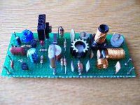
In this project, you will make a simple low-power broadcast-type circuit, using a crystal oscillator integrated circuit and an a collector modulated AM oscillator. You can connect the circuit to the an electrec microphone (pointed out in gray on the diagram) or amplified dynamic microphone (no amplified microphone has a to low output voltage to work. Approx. 100mv is needed). You could also add a LF preamp stage of one transistor to allow connecting a dynamic microphone directly.

You'll see that you can receive the signal through the air with almost any AM radio receiver. Although the circuits used in radio stations for AM receiving are far more complicated, this nevertheless gives a basic idea of the concept behind a principle transmitter. Plus it is a lot of fun when you actually have it working!
Remember that transmitting on 20 meter band you'll need a valid radioamateur license!

A wide range of different circuits have been used for AM, but one of the simplest circuits uses collector modulation applied via (for example) a transformer, while it is perfectly possible to create good designs using solid-state electronics as I applied here (T2 BD135).

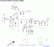
The transmitter is build as a Colpitts Oscillator with a strong 2N2219(A) transistor. HF-output of the oscillator is 400 to 600 mW, depending on the supply voltage of 10 to 15 Volts. The transmit frequency is stabilized with the 14.3Mhz crystal which can be bought in almost any electronicparts shop. A slight detuning of approx 2kc is possible by using C11 trimmer capacitor. The oscillator signal is taken from the collector of T2 by induction and via a low-feedthrough filter and guided to the output via an L-filter circuit cleaning up the signal pretty good. The oscillator is keyed by T1 and the morse key (S). By keying the morse-key T1 is not been used for modulation and is biased, hence lets T4 freely oscillate.

AM
5.gif

Amplitude Modulation (AM) is a process in which the amplitude of a radio frequency current is made to vary and modify by impressing an audio frequency current on it.
This was the first type of modulation used for communicating signals from one point to another and is still the simplest to understand.
A radio frequency current has a constant amplitude in absence of modulation and this constant amplitude RF carries no information, i.e. no audio intelligence and is of no use to radio telephone (voice communication), but has application in morse code communication.
In its basic form, amplitude modulation produces a signal with power concentrated at the carrier frequency and in two adjacent sidebands. Each sideband is equal in bandwidth to that of the modulating signal and is a mirror image of the other. Thus, most of the power output by an AM transmitter is effectively wasted: half the power is concentrated at the carrier frequency, which carries no useful information (beyond the fact that a signal is present); the remaining power is split between two identical sidebands, only one of which is needed.
CW
CW is the simplest form of modulation. The output of the transmitter is switched on and off, typically to form the characters of the Morse code.
CW transmitters are simple and inexpensive, and the transmitted CW signal doesn't occupy much frequency space (usually less than 500 Hz). However, the CW signals will be difficult to hear on a normal receiver; you'll just hear the faint quieting of the background noise as the CW signals are transmitted. To overcome this problem, shortwave and ham radio receivers include a beat frequency oscillator (BFO) circuit. The BFO circuit produces an internally-generated second carrier that "beats" against the received CW signal, producing a tone that turns on and off in step with the received CW signal. This is how Morse code signals are received on shortwave.

Although this design is primarely designed for AM, it can be used for CW by keying S.

RF Oscillator
Is been carried out by T4 (NPN 2N2219). This is the stage where the carrier frequency intended to be used is generated by means of Crystal Oscillator Circuitry or capacitance-inductance based Variable Frequency Oscillator (VFO). The RF oscillator is designed to have frequency stability (Xtal) and power delivered from it is of little bit more importance, although it delivers 600mW@12v , hence can be operated with low voltage power supply with little dissipation of heat. However, here we use the oscillator for a bit more power and so it does neet a heat sink.

You could add a switch (very short connections if using an ordinary switch) to select different Xtal's (frequencies). You could also use a more effective diode-based switch I've build here. This hasn't got the problems with longer connections at all.


Filter
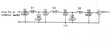
RF power amplification is also done here and this stage is coupled to the antenna system through antenna impedance matching circuitry (L1/L2/L3). Care is taken at this stage so that no harmonic frequency is generated which will cause interference in adjacent band (splatter) on other bands (C17...C21). This 3-element L-type narrow bandpass filter circuit and a low-pass filter for the desired frequency cleans out any remaining harmonic signals very efficiently hence good spectral purity.

Modulator
Is done by T1 and T2. Audio information is impressed upon the carrier frequency at this stage. Do to selective components circuits (C1,R1,R2,C2,C3,C4,C8) the voice component frequencies are enhanced, whilest others are suppressed (bandwidth +- 3kc/side) keeping it between HAM-radio specs.

Why over modulation is not desirable?..
Over modulation is not desirable, i.e. modulation should not exceed 100 %, because if modulation exceeds 100 % there is an interval during the audio cycle when the RF carrier is removed completely from the air thus producing distortion in the transmission.

Housing/shielding
The whole circuit needs to be mounted in an all-metal/aluminum case. If you're unable to obtain an all-metal case, then use a roll of self-sticking aluminum tape (available from your hardware store) or PVC box painted with graphite paint. Just make sure that all individual pieces of aluminum-tape (or the graphite paint) are conducting with each other. Works fine.

Use it with your receiver
If you put a relay, or better a transistor switch to mute your receiver (if equiped) you can easily make a QSO HI. A simple BC338, Bc547, 2N2222 (T3) at pin a" with the base biased with a 100k resistor, emmitor at the gnd and the collector fed to your receiver's mute input works fine. Or you can use a 12v relay... Every time you PTT the transistor (or when using a relay, the switch) is "shortened" between the ground, hence muting your receiver (again; if your receiver has mute capabilities).

[hide]
6.gif

[/hide]
Parts list 20-meterband transmitter

  • T1 BC338, BC337
  • T2 BD135 (with heatsink)
  • T3 2N2222, BC338
  • T4 2N2219A (with heatsink)
  • C1 220nF (polyester) rev1.2
  • C2 1500 pF (polyester) rev1.2
  • C3 10nF (polyester) rev1.2
  • C4 47uF/25v
  • C5 100nF
  • C6 100uF/25v
  • C7 100nF
  • C8 100nF
  • C10 12pF
  • C11 120pF (frequency offset +- 2kc)
  • C12 0...18pF (peek at design frequency Xtal)
  • C13,C14 330pF
  • C15 470pF
  • C16 47pF
  • C17= 6...40pF (white) set at half position and tune to max power
  • C18 22pF
  • C19 180pF
  • C20 220pF
  • C21 150pF
  • R1 1k
  • R2 3k3
  • R3 120
  • R4 560k
  • R5 560
  • R6 100 (pot. to set power/modulation ratio +/- 50mW according to applied voltage)
  • R7 100k
  • R8 4k7
  • R9 560
  • L1 = 0.8mm Cul (insulated copper wire), 15.5 turns close together, 7mm inside, tap at 6.5 turns
  • L2 = 0.6mm Cul (insulated copper wire), 24 turns close together, 8mm inside diameter
  • L2 = 0.6mm Cul (insulated copper wire), 8 turns close together, 8mm inside diameter
  • Ls2 = 470 1/2 watt carbon, 0,2 Cul turned 5 times over the entire length of the resistor (+/- 10uH)
  • Dr = small ferrite core with a few turns of 0,2 Cu (or the spare wire of R5 turned a few times through the core)
  • 14.310Mc Xtal (or other for your desired frequency) +- 2kc with C11
  • C1, C2, C3, C8 polyester film capacitor
Ls1, Ls2
20.jpg
Revision 1.1
Filter unit efficiency peaked by changing C19 & C20
BIAS T4 improved by changing R9 + adding ferrite in series

Revision 1.2
Audio modulation spectrum and linearity improved (changing C1,C2,C3)
Revision 1.3
Ls1 coil removed, C9 removed (extra choke was not needed)
Note:
Always use a dummy load for testing and adjusting the transmitter!!!
Specifications

  • Peak Frequency range: 14Mc...14.5Mc
  • Output RF power: 600mW pep @ 12v
  • AM modulated +/- 85% (CW if keyed)
  • Adjustable output impedance to 50 Ohms
  • Band-pass type harmonic L-filter + lowpass PII
  • Usable voltages: Vcc 9 - 15 volts
  • Average current I:140mA@12v
  • Xtal oscillator,
  • Adjustable frequency of 2Kc
  • LF input +/- 100mV @ +/- 4k
Antenna's
It's important to use a correct designed antenna according to band you would likt to operate, or at least a good tuned antenna using a matcher (protecting your transmitter). Several examples can be found on my website and all across the Web. A dipole is always a good alternitive (total length = 150/freq - 5%).
The performance (distance relative to you RF power) of your transmitter/transceiver is as importent (if not more) as the RF power you transmit! A dummy load gives also a perfect 1:1 SWR, but you wont get any farther then the street you live in HI. Finally, athmospheric conditions (D-,E-,F-layers depending on the frequency you're using) is as important as all the above.


w_mirzaii

کاربر
2013-03-12
121
219
کرمان
سلام
تشکر بابت وقتی که گذاشتید


برد این مدار که گذاشتین چند کیلومتر هست؟


نقشه رو من نمیتوتونم ببینم چرا؟
فکر کنم این باشه دیگه :


transmitter_HF_QRP_20meter_on6mu.jpg


transmitter_20meterband_QRP_on6mu.GIF
 
آخرین ویرایش:
  • Like
واکنش‌ها[ی پسندها]: 1212ali

2elyas

VIP+ افتخاری
کاربر
2012-01-30
405
1,560
سلام و درود به همه استادان
من یه ***** میان گذر 430mhz-440mhz میخام ببندم .
استاد عزیز لطف میکنید اگر برام طراحی کنید .
باز هم سپاس از شما
 
  • Like
واکنش‌ها[ی پسندها]: amer007

jfrras

مدير انجمن تخصصی الکترونیک
مدیر تالار
2007-04-13
3,122
74,158
48
ایران
سلام و درود به همه استادان
من یه ***** میان گذر 430mhz-440mhz میخام ببندم .
استاد عزیز لطف میکنید اگر برام طراحی کنید .
باز هم سپاس از شما


سلام

1.jpg
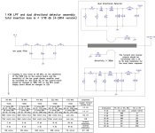
به جدول گوشه راست دقت کنید . و برای فرکانس مورد نظر سیم پیچ مناسب پیدا کنید.

[hide]schematic.jpg[/hide]
 

jojo_tabi

کاربر
2015-04-09
10
38
پاسخ : فرستنده fm استریوی استثنایی

با سلام :
بنا به درخواست سه نفر از دوستان گلم :
مداری که در حال حاضر شاهد ان هستید یک فرستنده FM استریوفونیک HI – FI ;مناسب برای ارسال صدای MP3 و تقریبا همه دستگاه های صوتی با کیفیت عالی و جمع و جور که با حداقل یک عدد باتری قلمی و برای داشتن حداکثر توان خروجی با یرد بیشتر را میتوانید تا دو عدد باتری قلمی (ماکزیمم سه ولت ) بکارگیرید .
در مونتاز مدار سعی کنید از قطعات مرغوب پیشنهاد شده استفاده کنید در مورد بوبین مدارکه شکلی از اماده انرا در عکس با وضوح بیشتر مشاهده می کنید تشکیل شده از سه و نیم دور سیم شماره 15 و کریستال بکار رفته نیز یک عدد 32 کیلوهرتز استوانه ای (در داخل ساعت های مچی ارزان قیمت و اسباب بازی ها بیابید ) میباشد و از یک ای سی مشهور BA1404 که دتا شیت انرا نیز تقدیم میکنم و مدار PCB در دو فرمت تهیه و دوستانیکه از گیرنده مونو ی FM استاندارد استفاده میکنند (برای حفظ کیفیت ) یک مدار انکودر و مولتی پلکسر NJM2035 را نیز تقدیم و برای اطلاعات بیشتر توضیحی هم از منبع اصلی را ببینید
Whether you want to create your own radio station, transmit the music around the house, or simply create a wireless link between your iPod and a receiver in your car, this transmitter will let you do these things easily. With BA1404 HI-FI Stereo transmitter you will be able to transmit MP3 music from your iPod, computer, discman, walkman, TV / SAT receiver, and many other audio sources.
The above FM transmitter design is a result of many hours of testing and tweaking. The goal was simple; to test many existing BA1404 transmitter designs, compare their performance, identify weaknesses and come up with a new BA1404 transmitter design that improves sound quality, has very good frequency stability, maximizes transmitter's range, and is fairly simple for everyone to build. We are happy to announce that this goal and expectations have been met and even exceeded.
The transmitter can work from a single 1.5V cell battery and provide excellent crystal clear stereo sound. It can also be supplied from two 1.5V battery cells to provide the maximum range.

L1 - 3.5 Turns Variable Coil
BA1404 IC
38KHz Crystal
ANT - 30 cm of copper wire

هر گونه مشگل یا سوالی داشتید در خدمتم .
با تشکر .
موفق باشید .

سلام استاد خسته نباشید. میشه لطف کنین عکس این مدارو دوباره بفرستین؟ عکس کامل باز نمیشن. اگه بصورت زیپ باشه عالی میشه. ممنون
 
بالا