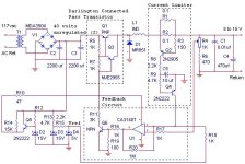
باسلام مدار زیر منبع تغذیه 5 تا 12 ولت 10 آمپر است با تغییر میتوانی به پاور مورد نظرت بررسی:
12Volt, 10 Amp Switching Power Supply
The switching power supply, shown in the schematic, provides 12 volts, at 10 amps, maximum, using a discrete transistor regulator with an op-amp functioning as a comparator in the feedback circuit. The supply was constructed in 1984 and is variable frequency, as opposed to the pulse width modulator (PWM) controllers used today

With reference to the schematic, the front panel power-on light is not shown. There is no adjustable current limiter in this unit, although R1, R2, R3, Q2, R8, R9, C5 and Q4 set the current limit to approximately 10 amps. As you can see, the design is very similar to that of a linear power supply, except that L1, and D1 have been added, and U1 operates in a switching mode as a comparator with a small amount of hystersis. The switching frequency of this unit varies with the output current drawn by the load. This is an undesireable feature, which is why PWM regulators are used today. With a PWM regulator, the switching frequency is constant and will produce spurs only at known discrete frequencies rather than spurs at all frequencies. The Darlington-connected pass transistor block in the schematic is there twice (in parallel) for robustness. R4 in an internal trim-pot that can set the output voltage anywhere between 5 to 15 volts
A more modern circuit might use a single switching IC regulator, from National Semiconductor, Linear Technology, Maxim, or many other numerous vendors. As a minimum, the D4 voltage reference could be replaced with a high precision LM4040 voltage reference which has excellent stability over temperature. My personal preference for a modern design is to use a PWM controller IC with an external MOSFET transistor since discrete TO-220 style MOSFETs can be obtained with 400 volt ratings and 80 amperes of current capability, making the supply virtually indestructable when linked with the protection circuits built into the PWM chip


