سلام خدمت علاقه مندان به الکترونیک خصوصا اعضای سایت ایران تی کی
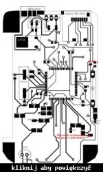
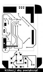
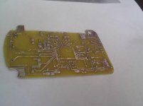
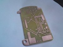
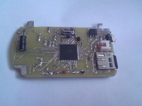
یک مدار قابل ساخت اسیلوسکوپ با AVR و ال سی دی رنگی موبایل خیلی جالب تقدیم به شما
 [hide]
 [/hide][hide]
 [/hide]
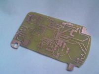 [hide]
 [/hide]
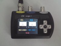
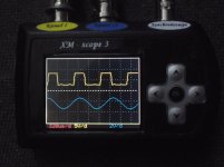
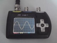
 مشاهده فایلپیوست Osciloscop PCB.rarمشاهده فایلپیوست HEX.rarمشاهده فایلپیوست txt.rar
این هم توضیحات به زبان اصلی
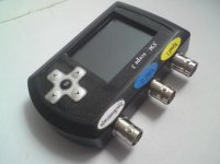
M-scope 3 - miniature two-channel digital oscilloscope for each. This is already the third version of the digital oscilloscope processor with AVR. This time the machine is more complex, added a lot of interesting and useful features, and above all, adding the device more practical applications.
The main objective of the project was to make a two-channel oscilloscope with the smallest dimensions, with low hardware complexity, so that everyone can do it at home. An important role played by the cost of performance and availability of parts.
The device
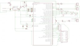
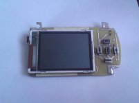
The heart device is a microcontroller ATXMega128A3-AU. The oscilloscope uses two built-in A / D converters of the microcontroller. The LCD display is a 132x176 pixel TFT driver L2F50 LS020 or the popular Siemensów S65/SX65/CX65 etc.
Description of parameters:
-Max sampling frequency in real time: 2 ms / s per channel
-Max frequency of equivalent-time sampling: 24 Ms / s
Amplitude-Resolution: 12 bits (11 bits + sign bit)
Input-voltage range (AC + / - 35V, DC 0-35V)
-Analog bandwidth <1 MHz
Frequency-range of measured waveforms in real time: 50Hz - 300kHz per channel
-Range of measured waveforms at frequencies equivalent: <1 MHz per channel for sinusoidal signals (or similar), periodic
Time-base in real time:
5us / d, 10us / d, 20us / d, 40us / d, 80us / d, 160us / d, 320us / d, 640us / d, 1.3ms / d, 2.5ms / d, 5 ms / d
Time-base time equivalent:
1.6us / d 800ns / d 400ns / d
-The voltage on the plot:
200mV / d, 0.5V / d, 1V / d, 2V / d, 5 V / d, 10 V / d, 20V / d (independent adjustment for each channel)
Description of functions:
-The ability to independently adjust the probe attenuation (1x, 10x, 100x) for each channel which changes the voltage value at the appropriate plot
-Infinitely adjustable vertical position of each of the waveforms on the screen
-Continuously adjustable trigger level
Auto-synchronization (software) with respect to the channel or turn off synchronization
-Release button
-External trigger signal (rising edge)
-External trigger signal (trailing edge)
-Amplitude measurement for each channel
-Frequency measurement for each channel
-Measurement of the maximum progress for each channel
-Measurement of the minimum course for each channel
-Measurement cursors:
* Cursors time
* Voltage Cursors
-Stopping course of
XY-mode deviation
-Spectrum analyzer uses FFT algorithm (frequency control terminal, the cursor measurement frequency)
-Digital interpolation filter (3x, 6x or 12x increases the sampling rate)
-Independent inversion of each of the waveforms
-Save up to 50 measurements on the micro SD card (can be measured naming)
-Reading measurements of micro SD card (the ability to perform most of the measurements on the course as it was read in real time)
-Voltmeter AC / DC 2-channel (instantaneous value or the average voltage)
CONSTRUCTION
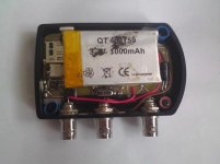
The device has been designed and made by me from the beginning, all made at home. This is a BETA far, any errors the program will come out, as it will użytkowało and I will keep improving. The oscilloscope takes about 70-80 mA of current, 1000mAh battery should then be enough for more than 10 hours.
یک مدار قابل ساخت اسیلوسکوپ با AVR و ال سی دی رنگی موبایل خیلی جالب تقدیم به شما

 [hide]
 [/hide][hide]
 [/hide]

 [hide]
 [/hide]


 مشاهده فایلپیوست Osciloscop PCB.rarمشاهده فایلپیوست HEX.rarمشاهده فایلپیوست txt.rar
این هم توضیحات به زبان اصلی
M-scope 3 - miniature two-channel digital oscilloscope for each. This is already the third version of the digital oscilloscope processor with AVR. This time the machine is more complex, added a lot of interesting and useful features, and above all, adding the device more practical applications.
The main objective of the project was to make a two-channel oscilloscope with the smallest dimensions, with low hardware complexity, so that everyone can do it at home. An important role played by the cost of performance and availability of parts.
The device
The heart device is a microcontroller ATXMega128A3-AU. The oscilloscope uses two built-in A / D converters of the microcontroller. The LCD display is a 132x176 pixel TFT driver L2F50 LS020 or the popular Siemensów S65/SX65/CX65 etc.
Description of parameters:
-Max sampling frequency in real time: 2 ms / s per channel
-Max frequency of equivalent-time sampling: 24 Ms / s
Amplitude-Resolution: 12 bits (11 bits + sign bit)
Input-voltage range (AC + / - 35V, DC 0-35V)
-Analog bandwidth <1 MHz
Frequency-range of measured waveforms in real time: 50Hz - 300kHz per channel
-Range of measured waveforms at frequencies equivalent: <1 MHz per channel for sinusoidal signals (or similar), periodic
Time-base in real time:
5us / d, 10us / d, 20us / d, 40us / d, 80us / d, 160us / d, 320us / d, 640us / d, 1.3ms / d, 2.5ms / d, 5 ms / d
Time-base time equivalent:
1.6us / d 800ns / d 400ns / d
-The voltage on the plot:
200mV / d, 0.5V / d, 1V / d, 2V / d, 5 V / d, 10 V / d, 20V / d (independent adjustment for each channel)
Description of functions:
-The ability to independently adjust the probe attenuation (1x, 10x, 100x) for each channel which changes the voltage value at the appropriate plot
-Infinitely adjustable vertical position of each of the waveforms on the screen
-Continuously adjustable trigger level
Auto-synchronization (software) with respect to the channel or turn off synchronization
-Release button
-External trigger signal (rising edge)
-External trigger signal (trailing edge)
-Amplitude measurement for each channel
-Frequency measurement for each channel
-Measurement of the maximum progress for each channel
-Measurement of the minimum course for each channel
-Measurement cursors:
* Cursors time
* Voltage Cursors
-Stopping course of
XY-mode deviation
-Spectrum analyzer uses FFT algorithm (frequency control terminal, the cursor measurement frequency)
-Digital interpolation filter (3x, 6x or 12x increases the sampling rate)
-Independent inversion of each of the waveforms
-Save up to 50 measurements on the micro SD card (can be measured naming)
-Reading measurements of micro SD card (the ability to perform most of the measurements on the course as it was read in real time)
-Voltmeter AC / DC 2-channel (instantaneous value or the average voltage)
CONSTRUCTION
The device has been designed and made by me from the beginning, all made at home. This is a BETA far, any errors the program will come out, as it will użytkowało and I will keep improving. The oscilloscope takes about 70-80 mA of current, 1000mAh battery should then be enough for more than 10 hours.
پیوستها
-
36.2 کیلوبایت بازدیدها: 691
آخرین ویرایش:


