اينم چند مدار ساده براي دانشجويان جهت كار در ربات مين ياب
Metal Detector MkII
updated 22-8-2006
This project is an extension of
Metal Detector MkI, and shows how metal objects are detected. It is the second in a series of circuits and allows a great deal of experimentation, especially if you have a CRO (Cathode Ray Oscilloscope) and a few items to detect. You can view the waveforms and see exactly how they alter as an object is brought into the field of the coil.
There are a number of ways to detect a metal object and alter the operation of a circuit so that an output is produced.
Metal detectors will detect ferrous (iron, steel, stainless steel) as well as non-ferrous (copper, tin, gold, lead, silver, aluminium) as well as alloys (brass, cupro-nickel, pewter etc).
Depending on the complexity of the circuit, a metal detector will be able to discriminate between a lump of gold and an aluminium ring-pull from a drink-can.
The circuit we have presented in this project is very simple and works on the principle of detecting the amplitude of a waveform. This is called AMPLITUDE MODULATION.
When a metal object is placed inside the detecting coil, some of the magnetic flux passes into the object and creates a current called an eddy-current. This "uses-up" some of the magnetic flux and thus less flux is available for the receiving coil.
This produces a lower output from the coil and causes the second transistor in the circuit to be turned OFF slightly and the voltage on the collector rises. This allows the third and fourth transistors to oscillate and pass a signal to the fifth transistor to drive a mini speaker.
As you can see, the circuit consists of a number of BUILDING BLOCKS. All you have to do is understand how each block works, and you will understand the whole circuit.
The concepts of TALKING ELECTRONICS is to explain how various building blocks operate so you can design your own projects. You can take any of the blocks and add them to your own project.
It will be necessary to connect them together correctly.
You can consider this circuit consists of three building blocks:
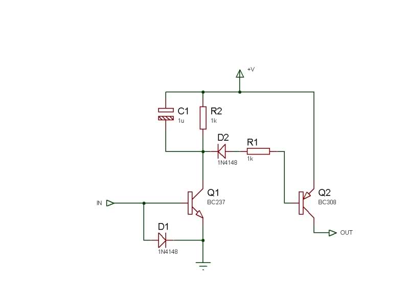
1. The first block is a FEEDBACK OSCILLATOR that gets its feedback via a transformer (the two coils act like a transformer). This uses the first two transistors.
The first transistor is turned on via the diode in the emitter of the second transistor. This diode receives its turn-on bias from the 1k8 resistor.
The resistance of the Rx (receiving coil) is very small and the base of the first transistor sees a "turn-on" voltage from the voltage across the diode.
The variable resistor in the emitter starts at a low value for our description of the circuit.
The first transistor has a high gain at this point in time and the Tx (transmitting coil) and 47n form a tuned circuit with a frequency of approx 15kHz.
The power rail is stabilized by the 5v6 zener and a small amount of noise is always present in any circuit and causes a small waveform to be produced by the inductor and capacitor.
This waveform is passed to the receiving coil (through the air) and a small voltage is produced by it.
Since the end of the receiving coil connected to the diode is fixed and rigid, the signal produced by the coil is passed to the base of both transistors. The coil is orientated so that the voltage it produces turns the first transistor ON harder and thus the waveform produced by the tuned circuit is increased.
Since the resistance of the pot is a minimum, the amplitude of the waveform will be a maximum and this will have the effect of turning ON the second transistor so that the voltage on the collector will be very low. The signal on the collector will be a waveform but this will be smoothed by the 100n capacitor.
As the resistance of the pot is increased, a voltage will appear at the emitter. Thus the base-to- emitter voltage will be LESS and the transistor will not be turned on as much. The waveform produced by the tuned circuit will reduce.
This will be reflected in the receiving coil and the second transistor will also get turned off slightly. The voltage on the collector will rise and this will be passed to the second building block . . .
2. THE VOLTAGE CONTROLLED OSCILLATOR
The voltage controlled oscillator is simply a direct-coupled high-gain amplifier with a 10n feedback capacitor to provide oscillation.
When a voltage appears on the base of the third transistor, it turns ON and this turns on the PNP transistor.
The voltage on the collector of the PNP transistor rises and this pulls one end of the 10n capacitor (via a 1k resistor) towards the positive rail.
The other end of the capacitor is connected to the base of the third transistor.
This turns ON the third transistor.
They keep turning ON until both are fully saturated (turned on). This happens very quickly and during this time the 10n capacitor starts to charge. The charging current flows through the base-emitter junction of the third transistor and as the capacitor charges, it develops a voltage across it. This causes the charging current to reduce. The third transistor gradually turns off and this turns the fourth transistor off slightly. The voltage on the collector of the fourth transistor drops and the voltage across the 10n capacitor causes the third transistor to turn off completely. This turns off the fourth transistor and now both are fully turned off.
The 10n discharges through the 56k and the cycle repeats.
As the voltage from the previous building block rises, the discharge-time for the capacitor is less and thus the frequency of the oscillator increases.
This is how the two-transistor direct-coupled amplifier turns into a variable-frequency oscillator.
3. THE DRIVER TRANSISTOR. The output of the oscillator is connected to a driver transistor via a 1k resistor. This resistor prevents high currents flowing when both transistors are turned on. The driver transistor is directly connected to an 8 ohm speaker. The 18R resistor reduces the volume and prevents large spikes appearing on the power rails. The result is a clicking sound.
For this type of circuit to be successful, the supply voltage must be maintained absolutely rigid for the detecting section. This is very difficult to do as the battery voltage changes as it gets older and all the semiconductor devices change according to the temperature. The supply voltage must be as stable as possible as the circuit is detecting a very small change in amplitude and the supply voltage has an effect on the size of the signal. The circuit uses a zener diode to create a fixed supply but as the temperature of the diode heats-up with current-flow, the circuit-settings change and a tone is gradually produced by the speaker. This has to be stopped by adjusting the pot on the emitter of the first transistor. This constant resetting of the circuit is called INSTABILITY and is one of the downfalls of the design.
However, for a simple circuit it offers very good sensitivity and an audio output.
CONSTRUCTION
The diameter of the wire and the size of the coil is not critical however our prototype was 0.5mm enamelled wire wound on an 80mm diameter former.
The two coils must be placed beside each other and changing the number of turns of the receiving coil does not alter the sensitivity of the circuit.
The transmitting coil is 50 turns and the detecting coil is 70 turns.
The two coils must be placed together and covered with tape to keep them together.
Make sure the 50t coil is connected across the 47n capacitor as the circuit will not work if the coils are exchanged. Don't worry about the correct connection of the second coil as it can be reversed if the circuit does not work.
The circuit will detect a small button cell about 5cm above the coil
PARTS LIST
au$xx.50 plus $4.50 post
us$xx.50 plus US$6.50 post
Order kit
1 - 18R all 0.25 watt
2 - 330R resistors
1 - 1k
1 - 1k8
2 - 10k
1 - 56k
1 - 220k
1 - 270k
1 - 1k mini pot
1 - 10n ceramic
1 - 47n ceramic
1 - 100n ceramic
1 - 1000u electrolytic
1 - 30metre 0.5mm enamelled winding wire
1 - 1N 4148 signal diode
1 - 5v6 zener diode
1 - 3mm red LED
3 - BC 547 transistors
1 - BC 557 transistor
1 - BC 338 transistor
1 - mini speaker
1 - 9v battery snap
1 - 9v battery
1 - 1m very fine solder
1 - Metal Detector MkII PCB